عربى

Content
- 1 Match the Reduction Ratio to the Propeller Curve
- 2 Torque Capacity and the Service Factor Buyers Should Ask For
- 3 Housing Layout, Alignment, and Hull Movement
- 4 Heat, Lubrication, and Clutch Duty
- 5 Gear Geometry, Materials, and Bearing Selection
- 6 Class Rules, Drawings, and Documentation
- 7 Why Engine Condition Sets the Design Margin
- 8 Commissioning Checks That Reveal Design Problems Early
- 9 Spare Parts Strategy Around the Gearbox
A 900 kW main engine at 1,800 rpm, a fixed pitch propeller, and a reduction ratio of 4.5 to 1. The vessel runs well for eight months. Then the oil temperature creeps up, the output seal starts weeping, and a bearing is found pitted at the next docking. Nothing was wrong with the gearbox itself. The propeller had been re-pitched and the engine was running above its rated point, so every revolution carried a heavier torque pulse than the design assumed.
Short version first. A marine gearbox design is settled by three decisions, in this order:
- Reduction ratio matched to the propeller curve and the engine rated speed.
- Torque capacity with a service factor that reflects real duty, not catalog duty.
- Housing, coupling, and lubrication design that survives hull movement, heat, and long slow-speed running.
Get those three right and the gearbox becomes a boring component. Get one wrong and it becomes the most expensive part on the boat.
Match the Reduction Ratio to the Propeller Curve
Propeller power absorption rises roughly with the cube of shaft speed, and that single relationship decides the ratio. The goal is not a round number. It is an engine that reaches rated speed while the propeller turns at the speed where it develops full thrust without overloading the engine.
Take an 1,800 rpm engine and a propeller whose best point is 400 rpm. The ratio is 4.5 to 1. Fit a 4.0 to 1 gearbox and the shaft turns at 450 rpm. Because absorbed power grows with the cube of speed, that propeller now demands about 40 percent more power than the engine can deliver at the same engine speed. The engine cannot reach rated rpm, the governor holds it at part load, and the exhaust runs hot. Go the other way with 5.0 to 1 and the shaft turns at 360 rpm, so the propeller absorbs only about 73 percent of its design power. The engine reaches rated speed easily and may overspeed at full rack, while the boat feels sluggish.
Most designers then check a light running margin of 4 to 7 percent, so the engine reaches about 104 to 107 percent of rated rpm on a clean hull in calm water. That margin pays for fouling, added weight, and a warm day later in the season.
Torque Capacity and the Service Factor Buyers Should Ask For
The ratio sets the speeds. Torque capacity decides whether the gears survive. Rated input torque comes from rated power and rated speed, and the service factor is the margin added on top. Most specification arguments happen at that margin, because it is the number that reflects how the vessel actually works.
| Parameter | What it defines | Typical value |
|---|---|---|
| Rated input torque | Continuous torque at the input shaft at rated engine power | 4,800 Nm at 1,800 rpm |
| Service factor | Margin above rated torque for duty, shock, and torque ripple | 1.5 to 2.0 |
| Reduction ratio | Engine speed divided by propeller shaft speed | 4.0 to 1 up to 5.5 to 1 |
| Mechanical efficiency | Power retained after gear, bearing, and seal losses | 0.96 to 0.98 |
| Helix angle | Tooth angle that spreads load across the face width | 8 to 15 degrees |
| Backlash | Clearance between meshing teeth at the pitch circle | 0.10 to 0.30 mm |
| Oil filtration | Cleanliness level the cooler and bearings expect | 10 micron nominal |
A tug needs a different margin than a displacement cruiser. Continuous high load fraction, frequent clutch work, and hours of trolling all raise the required factor. Ask for the calculation rather than the label. A factor of 1.5 means one thing on a boat running 300 hours a year at 60 percent load, and something else on a boat running 4,000 hours at 90 percent load. Peak torque rating, which covers clutch engagement and a propeller striking debris, belongs in the same conversation.
Housing Layout, Alignment, and Hull Movement
A gearbox bolted to the back of an engine looks rigid on the drawing. Afloat it is not. Hull flexing, engine mount compression, and thermal growth of the block all move the two flanges relative to each other, and the coupling has to absorb that movement. Early decisions include whether a down angle or a parallel offset is needed to clear the shaft log, how much offset the flexible coupling can accept, and whether the gearbox carries propeller thrust through its own bearings.
Thrust is the item buyers miss most often. A unit with an integral thrust bearing and one without look similar on a data sheet and are entirely different in installation. If a separate thrust block is required, it changes shaft length, foundation position, and the alignment procedure, so it has to be settled in the first sketch rather than at commissioning.
Heat, Lubrication, and Clutch Duty
Every kilowatt lost in gears, bearings, and seals becomes heat in the oil. A 900 kW input at 97 percent efficiency puts roughly 27 kW into the lubricant, and that heat has to leave through the cooler or the housing surface. Sizing the cooler for average load instead of continuous load is a common error on vessels that run long hours at high load fraction.
Oil choice and filtration matter as much as cooler size. Case hardened helical gears expect a specific viscosity grade and a clean supply, usually filtered in the 10 micron range. Oil temperature is the practical limit, with most designs holding normal operation under 80 degrees Celsius and alarming above 90. Clutch thermal rating is the other load that gets underestimated, because trolling and harbor maneuvering push energy into the plates rather than into the teeth.
Gear Geometry, Materials, and Bearing Selection
Marine reduction gears are almost always helical rather than spur. The helix angle spreads load across the face width, cuts noise, and smooths torque transfer, at the cost of an axial force the bearings and housing must carry. Typical angles sit between 8 and 15 degrees.
Gears are normally case hardened alloy steel with surface hardness of 58 to 62 HRC over a tough core. The accuracy grade of the flanks, the profile and lead corrections ground into the teeth, and the contact pattern recorded at assembly matter more than the headline steel grade. A gear set ground to a high grade but assembled with a poor contact pattern will whine, run hot, and fail early. Backlash is a design value with a tolerance band, not an accident, and it belongs in the drawing package.
Class Rules, Drawings, and Documentation
For a vessel under classification, or any owner who may sell the boat, the design file matters as much as the hardware. A complete package should contain rated torque and ratio with tolerances, the duty classification with the service factor calculation behind it, a torsional vibration analysis across the full operating range, gear geometry data with the contact pattern record, material and heat treatment certificates, and the oil specification with cooler performance curves. Ask for the torsional analysis early, because a design that reads well on paper can still place a critical speed inside the normal cruising range, and correcting that later is expensive.
Why Engine Condition Sets the Design Margin
Every gearbox calculation assumes a certain quality of torque at the input flange. Service factors, tooth root stresses, and bearing life estimates all rest on the engine delivering a reasonably even torque pulse, cylinder by cylinder, at rated firing pressure.
That assumption weakens with age. A cylinder head with worn valve seats or a leaking gasket changes compression, and uneven firing turns a smooth torque curve into a jagged one. The teeth still look fine on the drawing, but the dynamic load on them rises, and a design that was comfortable at a 1.6 service factor starts behaving like one at 1.3.
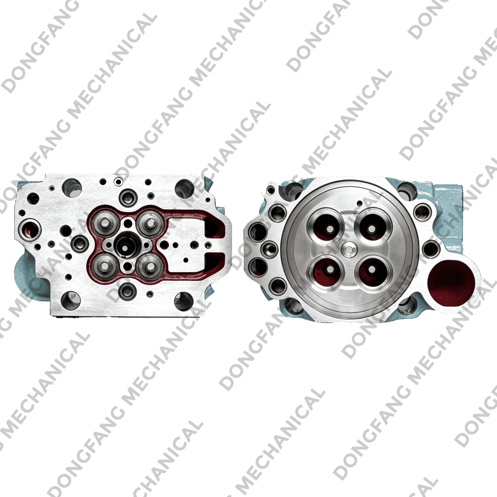
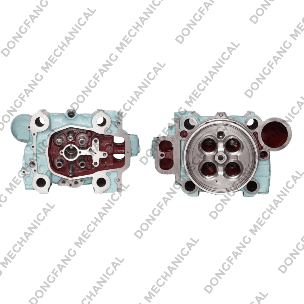
This is where engine and gearbox stop being separate projects. During a major overhaul, the condition of the combustion side is worth recording next to the gearbox inspection. Replacing a worn cylinder head with a correctly matched spare keeps the torque signature close to the value the reduction unit was designed around.
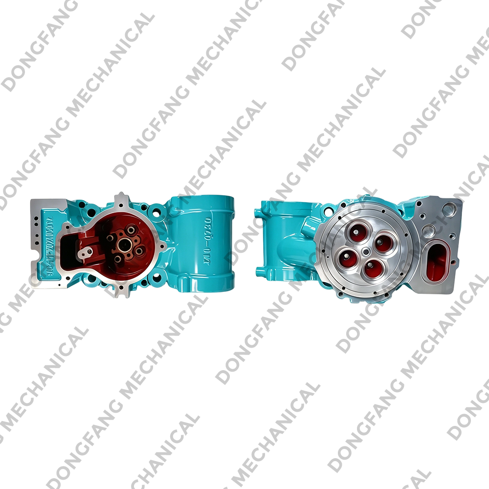 DONGFANG Cylinder Head for MAN Marine and Industrial EnginesThird-party compatible replacement cylinder head for MAN marine and industrial engines, relevant during overhauls when matched combustion components help preserve designed torque behavior.View Product →
Medium speed engines running at 500 to 750 rpm produce fewer but heavier pulses per revolution, so the gearbox has to be designed for a harsher input profile from the start, without relying on a generous margin to cover it.
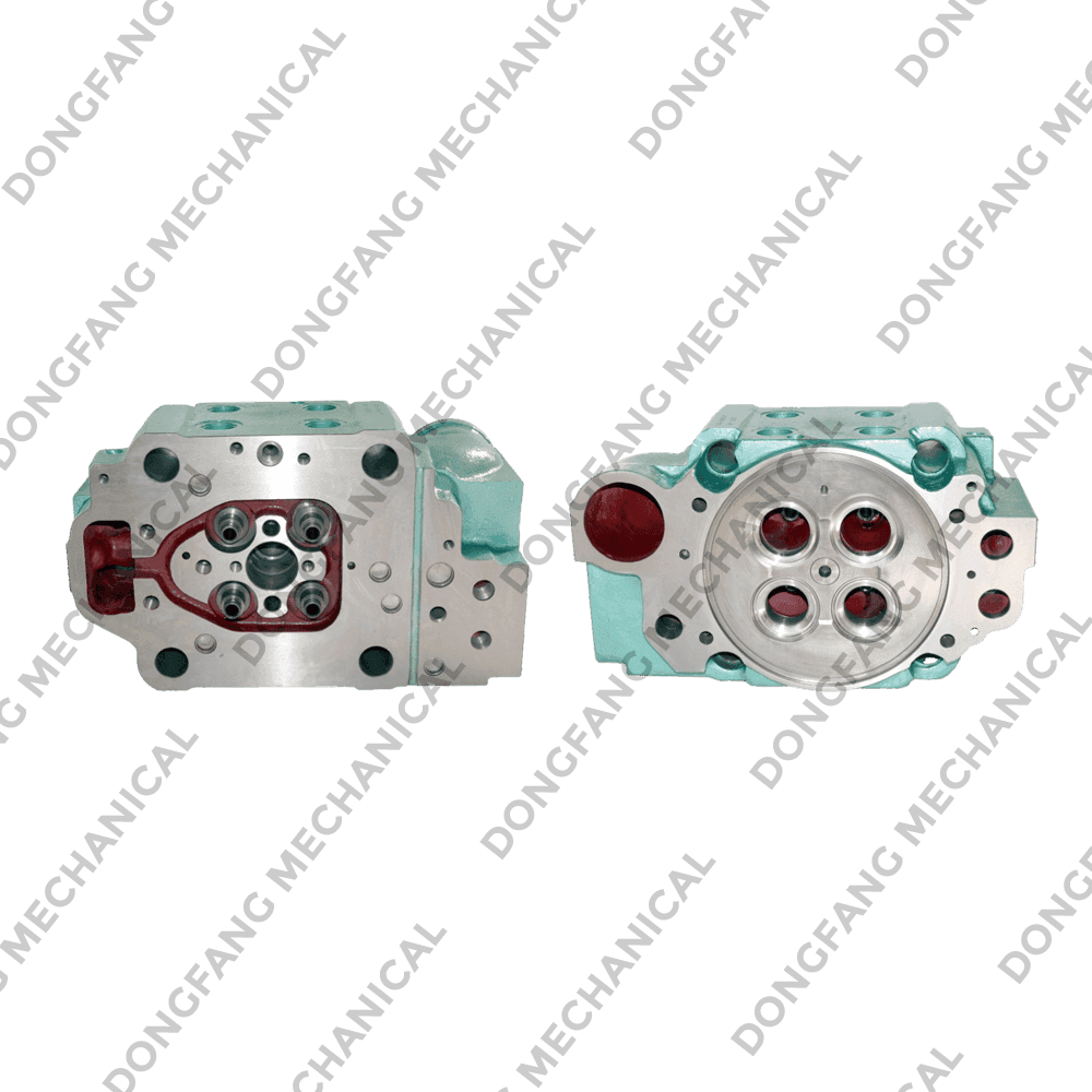
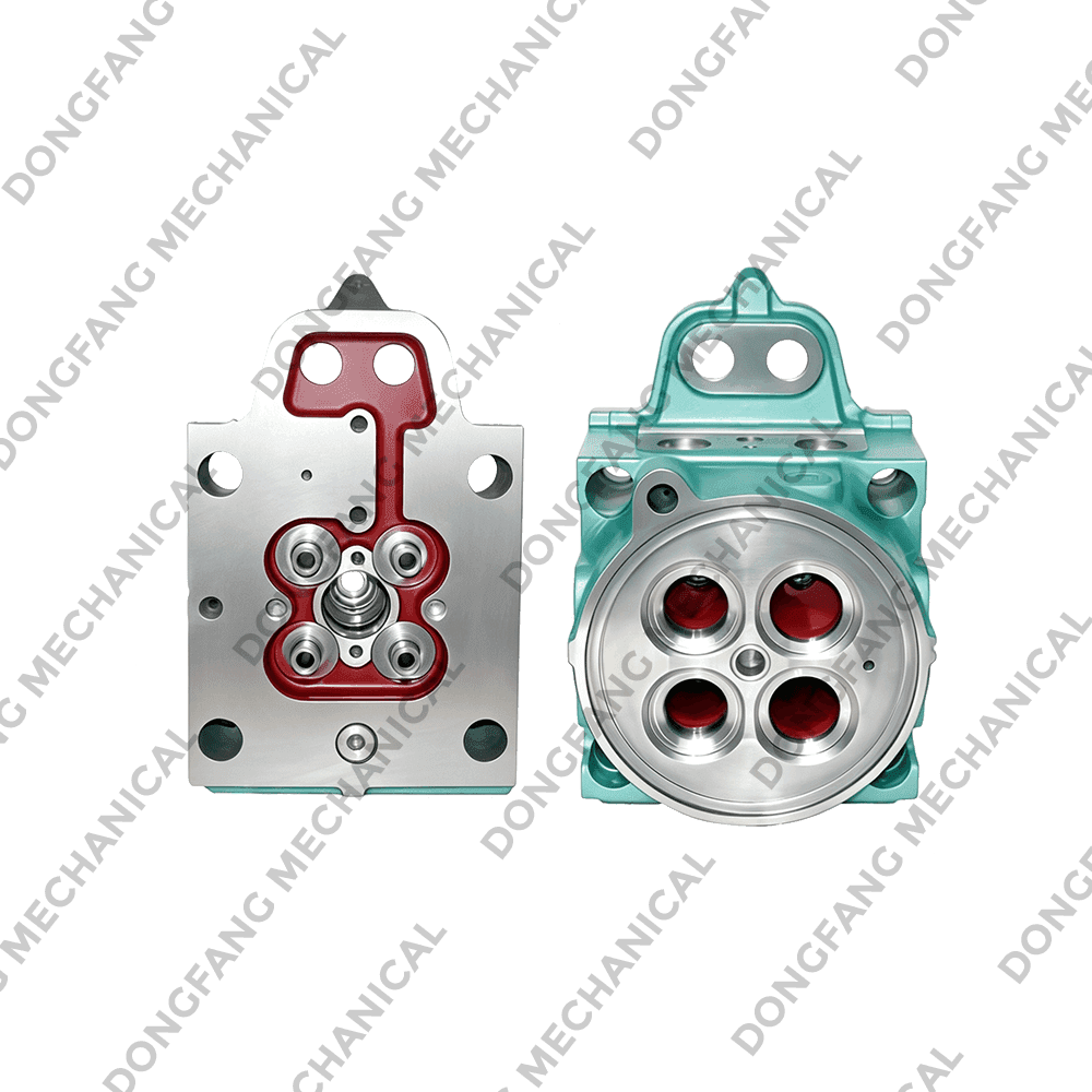 DONGFANG Cylinder Heads for Wartsila Marine Diesel EnginesAftermarket replacement cylinder heads for Wartsila R20, L20, R22, R25, and R32 engines, used in vessel and generator maintenance where engine condition affects drivetrain load.View Product →
On smaller work and fishing boats, where a 300 to 600 kW engine turns a propeller through a compact unit at 2.5 to 3.5 to 1, margins are tighter and engine condition matters more, because these installations hold a high load fraction for long periods.
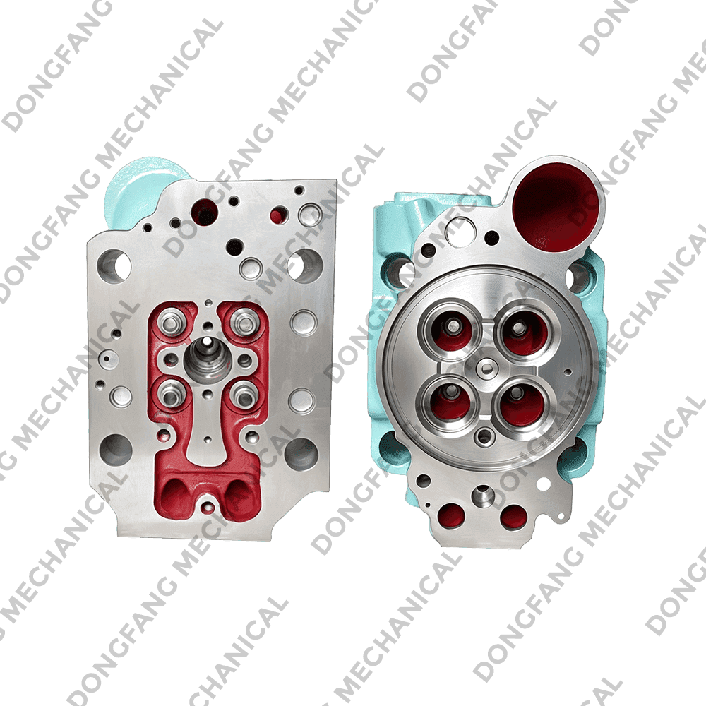
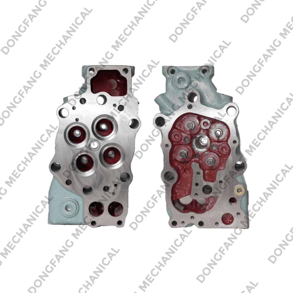 DONGFANG Cylinder Heads for Yanmar Marine Diesel EnginesAftermarket replacement cylinder heads for Yanmar models such as NY160, N165, N180, and EY220, intended for maintenance where engine condition matters under sustained load.View Product →
Commissioning Checks That Reveal Design Problems Early
The first 50 hours show whether the design assumptions hold. Record these at steady load and keep the numbers for comparison later:
- Cold and hot alignment readings at the coupling, afloat and at normal load.
- Oil pressure at idle, cruise, and full load against specified values.
- Oil temperature at cooler inlet and outlet after 30 minutes at continuous load.
- Vibration at input and output bearings, in velocity units, at several shaft speeds.
- Clutch engagement time and slip duration during a normal start.
- Oil sample at 50 hours and again at 250 hours for wear metal trends.
A unit that runs hot at cruise but normal at full load usually has a cooler or oil level problem. One that howls in a single speed band usually has a torsional or alignment issue. Both are cheaper to fix at the dock than at sea.
Spare Parts Strategy Around the Gearbox
Gearboxes are long lived and rarely the first thing to fail. The parts that need a strategy are the ones feeding torque into the unit: cylinder heads, valves, liners, and the bearing and seal sets inside the reduction gear.
For mixed fleets, organize spares by engine family rather than by vessel, because a head that fits one model is usually shared across a range. You can review the range on the product catalog page, or send the engine model and the propeller data together, so ratio, torque margin, and parts list are checked as one package instead of three separate conversations.