عربى
عربى 
Content
Valve cages and valve guides are a pair of fundamental supporting components in the engine's valve train, used to secure and guide the valves. If the valve is the "door," the valve seat is the "doorframe," then the valve cage is the "outer wall of the doorframe," and the valve guide is the "bushing on the door hinge."
Specifically:
-
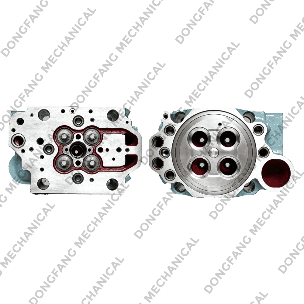
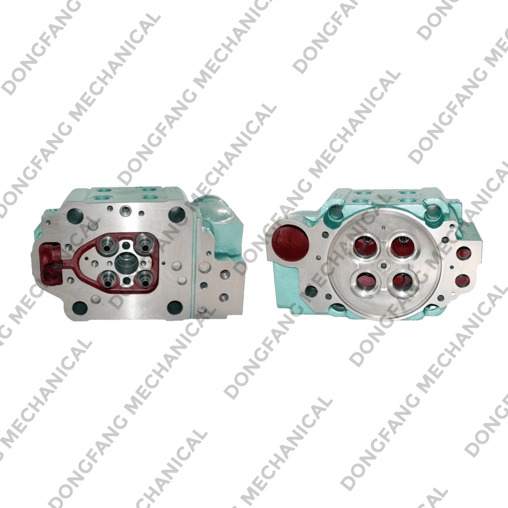
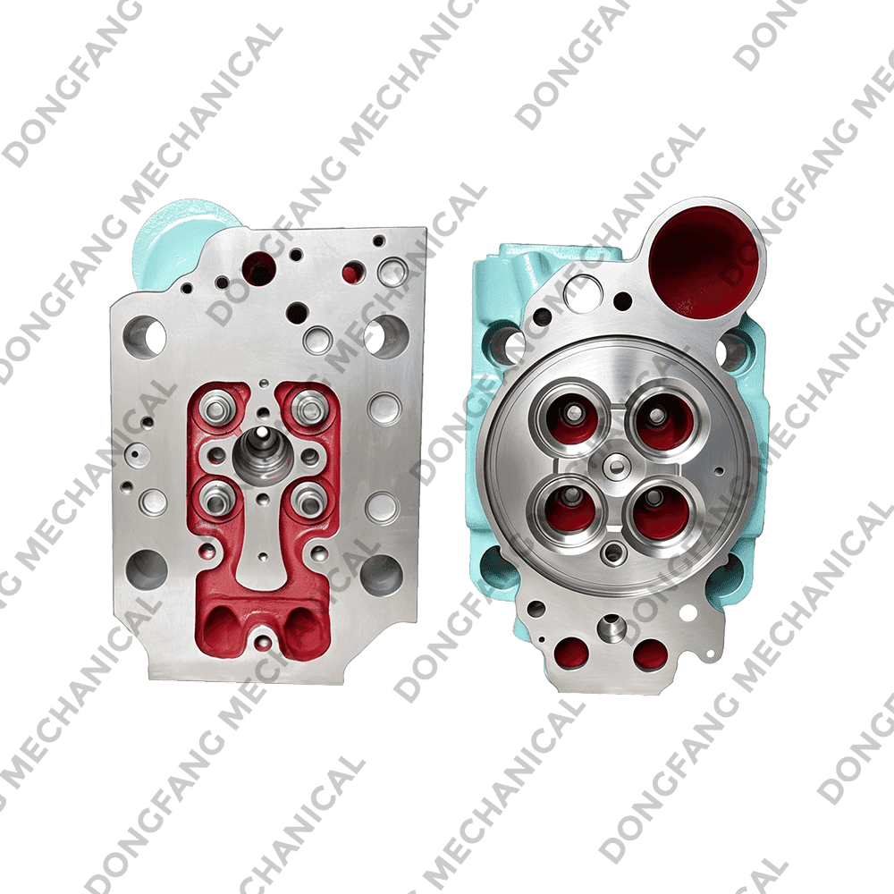
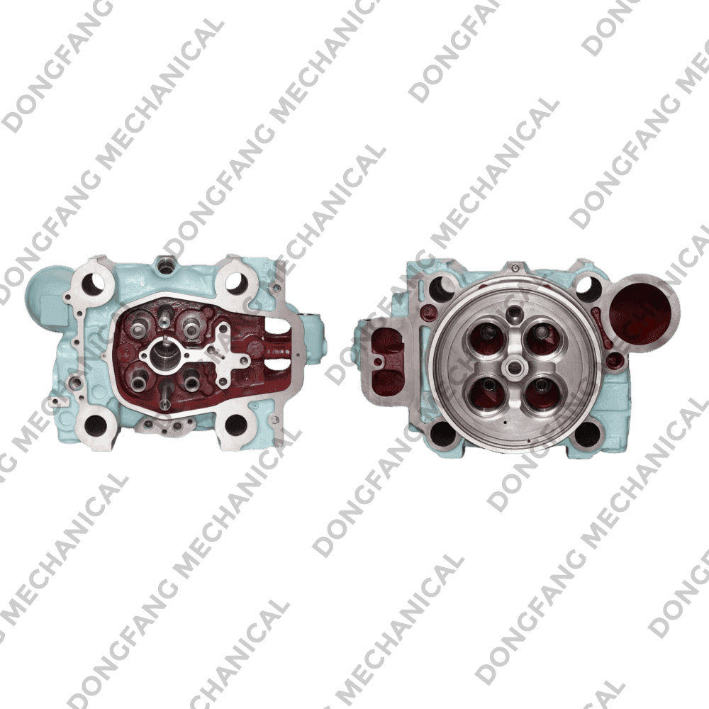
Valve Cage (Valve Guide Housing) – It is an independent, removable cylindrical or stepped metal assembly that integrates the valve seat and guide functions (or provides mounting positions for them). The valve cage is press-fitted into the cylinder head as a complete unit for the valve passage. Its main advantage is that when the seat or guide becomes worn, the entire valve cage can be replaced directly, eliminating the need for complex reaming and repair work on the cylinder head. This makes maintenance very convenient. It is commonly found in large diesel engines or older engine designs.
-
Valve Guide – It is a separate, hollow cylindrical bushing press-fitted into the cylinder head (or valve cage). Its inner bore precisely mates with the valve stem to provide guidance for the valve's up-and-down motion, ensuring that the valve always lands exactly in the center of the valve seat. Additionally, it serves a heat dissipation function, transferring heat accumulated at the valve stem head to the cylinder head or valve cage, where it is then carried away by the cooling system.
How do they work together?
When the valve moves up and down under the drive of the camshaft, the valve guide acts like a "track," constraining the valve stem to linear motion only, preventing it from wobbling or deviating sideways. This ensures that the valve head's tapered surface aligns precisely with the valve seat for a proper seal. The valve cage, on the other hand, acts as an "integrated module," consolidating the mounting positions for the valve, seat, and guide into a single assembly before being installed into the cylinder head.
Operating environment and common issues
Although they are not directly exposed to high-temperature combustion gases from the combustion chamber, their working conditions are still demanding:
-
Heat conduction – The guide continuously absorbs significant heat transferred from the valve stem, which can lead to oil coking at high temperatures.
-
Side wear – Despite guidance, the valve stem still exerts slight lateral forces on the inner wall of the guide during movement, which over time can cause the guide bore to wear into an oval shape.
-
Carbon buildup and sticking – Oil vapor oxidizes at high temperatures in the upper portion of the guide, forming carbon deposits that may reduce the clearance between the valve stem and guide, causing the valve to move sluggishly or even seize.
Materials and maintenance tips
-
Valve Guide – Commonly made from gray cast iron, powder metallurgy, or copper-based alloys, offering good self-lubricating properties and wear resistance. A proper running clearance must be maintained between the guide and valve stem (typically around 0.03–0.10 mm, depending on the engine type). Too little clearance causes sticking; too much leads to gas leakage, oil consumption, and abnormal noise.
-
Valve Cage – Typically manufactured from alloy steel or ductile iron, requiring high strength and thermal stability.
In routine maintenance, checking the clearance between the valve stem and guide is one of the standard service items. If the clearance exceeds specifications:
-
For engines with separate guides, the guide usually needs to be replaced (pressing out the old guide with a special tool, pressing in a new one, and then reaming the bore to size).
-
For engines with valve cages, it is often more economical and quicker to simply replace the entire valve cage assembly.